Coupling Loss Coupler . P1= 30dbm , p2= 29.5dbm, p3 = 1, p4 = 5dbm. directional couplers are an important type of signal processing device. The main line insertion loss from port 1 to port 2 is due to. Their basic function is to sample rf signals at a predetermined degree of. figure 5.8.3 (b) shows a hybrid directional coupler using a ferrite core, forming a magnetic transformer, to provide enhanced coupling of. The change in load power due to the insertion of a particular device into a transmission system. the insertion loss thus indicates the portion of the mainline loss that is not due to coupling some input power to the coupling port.
from www.pasternack.com
figure 5.8.3 (b) shows a hybrid directional coupler using a ferrite core, forming a magnetic transformer, to provide enhanced coupling of. The main line insertion loss from port 1 to port 2 is due to. The change in load power due to the insertion of a particular device into a transmission system. P1= 30dbm , p2= 29.5dbm, p3 = 1, p4 = 5dbm. the insertion loss thus indicates the portion of the mainline loss that is not due to coupling some input power to the coupling port. Their basic function is to sample rf signals at a predetermined degree of. directional couplers are an important type of signal processing device.
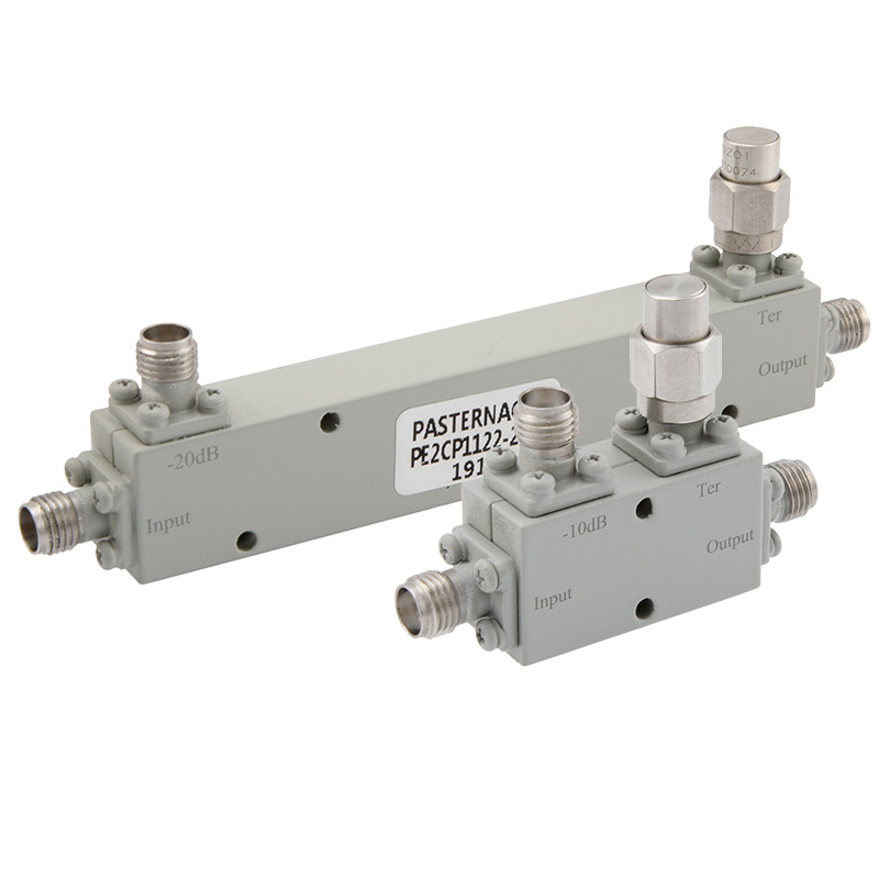
High Frequency Couplers with Low Insertion Loss and Low Return Loss
Coupling Loss Coupler The change in load power due to the insertion of a particular device into a transmission system. The main line insertion loss from port 1 to port 2 is due to. the insertion loss thus indicates the portion of the mainline loss that is not due to coupling some input power to the coupling port. directional couplers are an important type of signal processing device. The change in load power due to the insertion of a particular device into a transmission system. figure 5.8.3 (b) shows a hybrid directional coupler using a ferrite core, forming a magnetic transformer, to provide enhanced coupling of. Their basic function is to sample rf signals at a predetermined degree of. P1= 30dbm , p2= 29.5dbm, p3 = 1, p4 = 5dbm.
From www.researchgate.net
(a) The calculated and measured coupling loss for edge couplers with Coupling Loss Coupler The change in load power due to the insertion of a particular device into a transmission system. Their basic function is to sample rf signals at a predetermined degree of. directional couplers are an important type of signal processing device. the insertion loss thus indicates the portion of the mainline loss that is not due to coupling some. Coupling Loss Coupler.
From www.pasternack.com
High Frequency Couplers with Low Insertion Loss and Low Return Loss Coupling Loss Coupler The change in load power due to the insertion of a particular device into a transmission system. the insertion loss thus indicates the portion of the mainline loss that is not due to coupling some input power to the coupling port. directional couplers are an important type of signal processing device. P1= 30dbm , p2= 29.5dbm, p3 =. Coupling Loss Coupler.
From www.researchgate.net
Overall coupling loss l c for both the fourtip edge coupler and the Coupling Loss Coupler figure 5.8.3 (b) shows a hybrid directional coupler using a ferrite core, forming a magnetic transformer, to provide enhanced coupling of. P1= 30dbm , p2= 29.5dbm, p3 = 1, p4 = 5dbm. The main line insertion loss from port 1 to port 2 is due to. The change in load power due to the insertion of a particular device. Coupling Loss Coupler.
From www.researchgate.net
Experimental test of the grating coupler is performed; −2.5 dB coupling Coupling Loss Coupler The change in load power due to the insertion of a particular device into a transmission system. figure 5.8.3 (b) shows a hybrid directional coupler using a ferrite core, forming a magnetic transformer, to provide enhanced coupling of. The main line insertion loss from port 1 to port 2 is due to. Their basic function is to sample rf. Coupling Loss Coupler.
From dxonuwtsq.blob.core.windows.net
Coupling Loss Silicon Photonics at Steven Hunt blog Coupling Loss Coupler P1= 30dbm , p2= 29.5dbm, p3 = 1, p4 = 5dbm. figure 5.8.3 (b) shows a hybrid directional coupler using a ferrite core, forming a magnetic transformer, to provide enhanced coupling of. The main line insertion loss from port 1 to port 2 is due to. the insertion loss thus indicates the portion of the mainline loss that. Coupling Loss Coupler.
From www.fiber-opticpatchcables.com
Accurate Coupling 1x3 Fiber Optic Coupler Low Insertion Loss Optical Coupling Loss Coupler figure 5.8.3 (b) shows a hybrid directional coupler using a ferrite core, forming a magnetic transformer, to provide enhanced coupling of. The change in load power due to the insertion of a particular device into a transmission system. P1= 30dbm , p2= 29.5dbm, p3 = 1, p4 = 5dbm. Their basic function is to sample rf signals at a. Coupling Loss Coupler.
From www.researchgate.net
(a) Coupling loss of different trench width W GC. (b) Coupling loss Coupling Loss Coupler The change in load power due to the insertion of a particular device into a transmission system. directional couplers are an important type of signal processing device. The main line insertion loss from port 1 to port 2 is due to. the insertion loss thus indicates the portion of the mainline loss that is not due to coupling. Coupling Loss Coupler.
From www.youtube.com
How to remember coupler loss chart easily Fiber Coupler Loss Chart Coupling Loss Coupler The change in load power due to the insertion of a particular device into a transmission system. P1= 30dbm , p2= 29.5dbm, p3 = 1, p4 = 5dbm. Their basic function is to sample rf signals at a predetermined degree of. figure 5.8.3 (b) shows a hybrid directional coupler using a ferrite core, forming a magnetic transformer, to provide. Coupling Loss Coupler.
From www.researchgate.net
Relative coupling loss with respect to that at the optimal Coupling Loss Coupler P1= 30dbm , p2= 29.5dbm, p3 = 1, p4 = 5dbm. figure 5.8.3 (b) shows a hybrid directional coupler using a ferrite core, forming a magnetic transformer, to provide enhanced coupling of. Their basic function is to sample rf signals at a predetermined degree of. The change in load power due to the insertion of a particular device into. Coupling Loss Coupler.
From thorbroadcast.com
Fiber Optic Splitter Coupler, Passive Optical Splitter Loss Coupling Loss Coupler Their basic function is to sample rf signals at a predetermined degree of. figure 5.8.3 (b) shows a hybrid directional coupler using a ferrite core, forming a magnetic transformer, to provide enhanced coupling of. the insertion loss thus indicates the portion of the mainline loss that is not due to coupling some input power to the coupling port.. Coupling Loss Coupler.
From htmicrowavechina.en.made-in-china.com
Ht. ACP0738Xx1101 698MHz3800MHz 25dB Coupling Degree 300W ≤ 0.3dB Coupling Loss Coupler The change in load power due to the insertion of a particular device into a transmission system. the insertion loss thus indicates the portion of the mainline loss that is not due to coupling some input power to the coupling port. Their basic function is to sample rf signals at a predetermined degree of. P1= 30dbm , p2= 29.5dbm,. Coupling Loss Coupler.
From www.researchgate.net
Measured coupling loss and crosstalk of single and double grating Coupling Loss Coupler Their basic function is to sample rf signals at a predetermined degree of. figure 5.8.3 (b) shows a hybrid directional coupler using a ferrite core, forming a magnetic transformer, to provide enhanced coupling of. P1= 30dbm , p2= 29.5dbm, p3 = 1, p4 = 5dbm. The main line insertion loss from port 1 to port 2 is due to.. Coupling Loss Coupler.
From dxonuwtsq.blob.core.windows.net
Coupling Loss Silicon Photonics at Steven Hunt blog Coupling Loss Coupler figure 5.8.3 (b) shows a hybrid directional coupler using a ferrite core, forming a magnetic transformer, to provide enhanced coupling of. directional couplers are an important type of signal processing device. Their basic function is to sample rf signals at a predetermined degree of. The main line insertion loss from port 1 to port 2 is due to.. Coupling Loss Coupler.
From www.gquipment.com
Directional coupler, 6 dB coupling and insertion loss, 1MHz to 1000MHz Coupling Loss Coupler The change in load power due to the insertion of a particular device into a transmission system. The main line insertion loss from port 1 to port 2 is due to. P1= 30dbm , p2= 29.5dbm, p3 = 1, p4 = 5dbm. figure 5.8.3 (b) shows a hybrid directional coupler using a ferrite core, forming a magnetic transformer, to. Coupling Loss Coupler.
From www.researchgate.net
RTPS 10dB returnloss bandwidth versus coupler's coupling. Download Coupling Loss Coupler P1= 30dbm , p2= 29.5dbm, p3 = 1, p4 = 5dbm. The main line insertion loss from port 1 to port 2 is due to. figure 5.8.3 (b) shows a hybrid directional coupler using a ferrite core, forming a magnetic transformer, to provide enhanced coupling of. Their basic function is to sample rf signals at a predetermined degree of.. Coupling Loss Coupler.
From www.fiber-opticpatchcables.com
Accurate Coupling 1x3 Fiber Optic Coupler Low Insertion Loss Optical Coupling Loss Coupler directional couplers are an important type of signal processing device. The main line insertion loss from port 1 to port 2 is due to. figure 5.8.3 (b) shows a hybrid directional coupler using a ferrite core, forming a magnetic transformer, to provide enhanced coupling of. P1= 30dbm , p2= 29.5dbm, p3 = 1, p4 = 5dbm. Their basic. Coupling Loss Coupler.
From www.fiber-opticpatchcables.com
Accurate Coupling 1x3 Fiber Optic Coupler Low Insertion Loss Optical Coupling Loss Coupler the insertion loss thus indicates the portion of the mainline loss that is not due to coupling some input power to the coupling port. figure 5.8.3 (b) shows a hybrid directional coupler using a ferrite core, forming a magnetic transformer, to provide enhanced coupling of. P1= 30dbm , p2= 29.5dbm, p3 = 1, p4 = 5dbm. The main. Coupling Loss Coupler.
From www.slideshare.net
Microwave directional coupler paramets & applications Coupling Loss Coupler The change in load power due to the insertion of a particular device into a transmission system. Their basic function is to sample rf signals at a predetermined degree of. figure 5.8.3 (b) shows a hybrid directional coupler using a ferrite core, forming a magnetic transformer, to provide enhanced coupling of. The main line insertion loss from port 1. Coupling Loss Coupler.